ASE Certification Training Headquarters

Online ASE Certification Training and Career Center

Welcome to ASE Certification Training Headquarters! We have everything you need to make your life easier as you begin your career as an Automotive Service Excellence Certified Master Mechanic. State specific training requirements, a step-by-step hiring process, potential employers, and interviews to help you get hired are just some of the helpful things you'll find here.

Diesel Exhaust Particulate Filters, Regeneration, and Ash Loading

Diesel Exhaust Particulate Filter

Purpose and Function

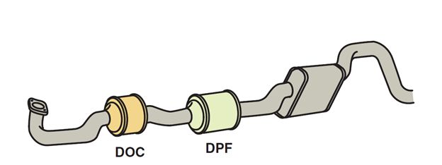
Diesel exhaust particulate filters (DPFs) are used in all light-duty diesel vehicles, since 2007, to meet the exhaust emissions standards. The heated exhaust gas from the DOC flows into the DPF, which captures diesel exhaust gas particulates (soot) to prevent them from being released into the atmosphere. This is done by forcing the exhaust through a porous cell which has a silicon carbide substrate with honeycomb-cell-type channels that trap the soot.

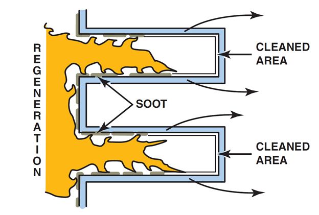
The main difference between the DPF and a typical catalyst filter is that the entrance to every other cell channel in the DPF substrate is blocked at one end. So instead of flowing directly through the channels, the exhaust gas is forced through the porous walls of the blocked channels and exits through the adjacent open-ended channels. This type of filter is also referred to as a “wall-flow” filter.

Diesel Oxidation Catalyst and Diesel Exhaust Particulate Filters

Diesel Oxidation Catalyst and Diesel Exhaust Particulate Filters Handle Diesel Exhaust

Operation

Soot particulates in the gas remain trapped on the DPF channel walls where, over time, the trapped particulate matter will begin to clog the filter. The filter must therefore be purged periodically to remove accumulated soot particles. The process of purging soot from the DPF is described as regeneration. When the temperature of the exhaust gas is increased, the heat incinerates the soot particles trapped in the filter and is effectively renewed.

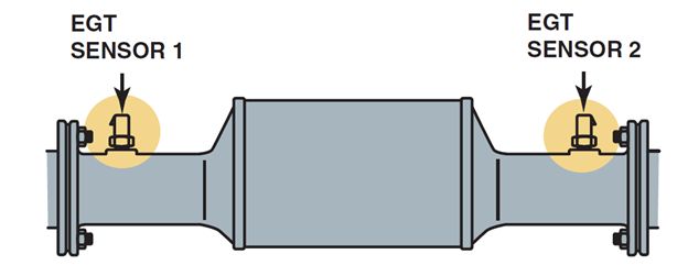
Exhaust Gas Temperature Sensors

Exhaust Gas Temperature Sensors EGT1 EGT2

EGT 1 and EGT2 are used by the PCM to help control after treatment

The following two exhaust gas temperature sensors are used to help the PCM control the DPF.

  • EGT sensor 1 is positioned between the DOC and the DPF where it can measure the temperature of the exhaust gas entering the DPF.
  • EGT sensor 2 measures the temperature of the exhaust gas stream immediately after it exits the DPF.

The powertrain control module monitors the signals from the EGT sensors as part of its calibrations to control DPF regeneration. Proper exhaust gas temperatures at the inlet of the DPF are crucial for proper operation and for starting the regeneration process. Too high a temperature at the DPF will cause the DPF substrate to melt or crack. Regeneration will be terminated at temperatures above 1,470°F (800°C). With too low a temperature, self-regeneration will not fully complete the soot-burning process.

DPF Differential Pressure Sensor

The DPF differential pressure sensor (DPS) has two pressure sample lines.

  1. One line is attached before the DPF.
  2. The other is located after the DPF.

The exact location of the DPS varies by vehicle model type such as medium duty, pickup, or van. By measuring the exhaust supply (upstream) pressure from the DOC, and the post DPF (downstream) pressure, the PCM can determine differential pressure, also called “delta” pressure, across the DPF. Data from the DPF differential pressure sensor is used by the PCM to calibrate for controlling DPF exhaust system operation.

Diesel Particulate Filter Regeneration

The primary reason for soot removal is to prevent the buildup of exhaust back pressure. Excessive back pressure increases fuel consumption, reduces power output, and can potentially cause engine damage. Several factors can trigger the diesel PCM to perform regeneration, including:

  • Distance since last DPF regeneration
  • Fuel used since last DPF regeneration
  • Engine run time since last DPF regeneration
  • Exhaust differential pressure across the DPF

DPF Regeneration Process

A number of engine components are required to function together for the regeneration process to be performed, as follows:

  1. PCM controls that impact DPF regeneration include late post injections, engine speed, and adjusting fuel pressure.
  2. Adding late post injection pulses provides the engine with additional fuel to be oxidized in the DOC, which increases exhaust temperatures entering the DPF to 900°F (500°C) or higher.
  3. The intake air valve acts as a restrictor that reduces air entry to the engine, which increases engine operating temperature.
  4. The intake air heater may also be activated to warm intake air during regeneration.

Types of DPF Regeneration

DPF Regeneration Passive Active Soot Cleaning

Regeneration burns the soot and renews the Diesel Exhaust Particulate Filter

DPF regeneration can be initiated in a number of ways, depending on the vehicle application and operating circumstances. The two main regeneration types are as follows:

  • Passive regeneration. During normal vehicle operation when driving conditions produce sufficient load and exhaust temperatures, passive DPF regeneration may occur. This passive regeneration occurs without input from the PCM or the driver. A passive regeneration may typically occur while the vehicle is being driven at highway speed or towing a trailer.
  • Active regeneration. Active regeneration is commanded by the PCM when it determines that the DPF requires it to remove excess soot buildup and conditions for filter regeneration have been met. Active regeneration is usually not noticeable to the driver. The vehicle needs to be driven at speeds above 30 mph for approximately 20 to 30 minutes to complete a full regeneration. During regeneration, the exhaust gases reach temperatures above 1,000°F (550°C). Active regeneration is usually not noticeable to the driver.

Ash Loading

Regeneration will not burn off ash. Only the particulate matter (PM) is burned off during regeneration. Ash is a noncombustible by-product from normal oil consumption. Ash accumulation in the DPF will eventually cause a restriction in the particulate filter. To service an ash-loaded DPF, the DPF will need to be removed from the vehicle and cleaned or replaced. Low ash content engine oil (API CJ-4) is required for vehicles with the DPF system. The CJ-4 rated oil is limited to 1% ash content.

Next Steps towards ASE Certification

Now that you’re familiar with Exhaust Gas Filtration, Regeneration, and Conversion, try out our free Automotive Service Excellence Tests to see how much you know!

Diesel Engine Catalyst

Catalyst Purpose and Function

Diesel oxidation catalysts (DOC) are used in all light-duty diesel engines, since 2007. They consist of a flow-through honeycomb-style substrate structure that is wash coated with a layer of catalyst materials, similar to those used in a gasoline engine catalytic converter. These materials include the precious metals platinum and palladium, as well as other base metal catalysts.

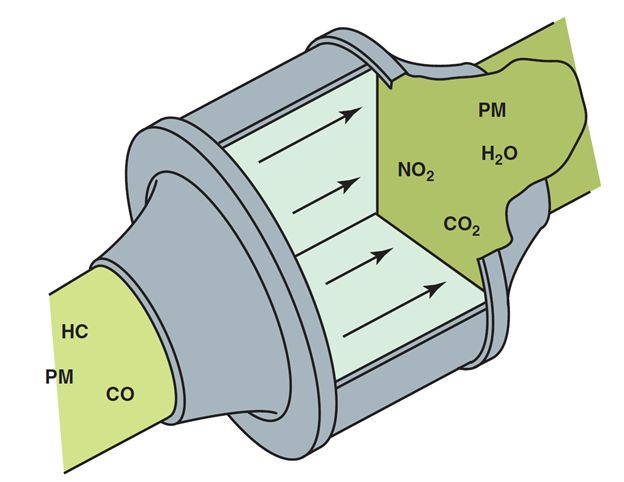
Catalysts chemically react with exhaust gas to convert harmful nitrogen oxide into nitrogen dioxide, and to oxidize absorbed hydrocarbons. The chemical reaction acts as a combustor for the unburned fuel that is characteristic of diesel compression ignition. The main function of the DOC is to start a regeneration event by converting the fuel-rich exhaust gases to heat.

The DOC also reduces:

  • Carbon monoxide (CO)
  • Hydrocarbons (HC)

Odor-causing compounds such as aldehydes and sulfur

Diesel Oxidation Catalyst

Chemical reaction within the Diesel Oxidation Catalyst

Next Steps towards ASE Certification

Now that you’re familiar with Diesel Engine Catalysts, try out our free Automotive Service Excellence Tests to see how much you know!

What is a Variable Vane Turbocharger?

Background

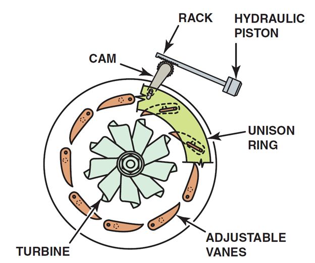
A variable turbocharger is used on many diesel engines for boost control. Boost pressure is controlled independent of engine speed and a wastegate is not needed. The adjustable vanes mount to a unison ring that allows the vanes to move. As the position of the unison ring rotates, the vanes change angle.

The vanes are opened to minimize flow at the turbine and exhaust back pressure at low engine speeds. To increase turbine speed, the vanes are closed. The velocity of the exhaust gases increases, as does the speed of the turbine. The unison ring is connected to a cam that is positioned by a rack-and-pinion gear. The vane position actuator solenoid connects to a hydraulic piston, which moves the rack to rotate the pinion gear and cam.

The turbocharger vane position control solenoid valve is used to advance the unison ring’s relationship to the turbine and thereby articulate the vanes. This solenoid actuates a spool valve that applies oil pressure to either side of a piston. Oil flow has three modes: apply, hold, and release.

  • Apply moves the vanes toward a closed position.
  • Hold maintains the vanes in a fixed position.
  • Release moves the vanes toward the open position.
Variable Vane Turbocharger

The following figure shows a variable vane turbocharger, which allows the boost to be controlled without the need of a wastegate.

The turbocharger vane position actuation is controlled by the ECM, which can change turbine boost efficiency independent of engine speed. The ECM provides a control signal to the valve solenoid along with a low-side reference. A pulse-width-modulated signal from the ECM moves the valve to the desired position.

Next Steps towards ASE Certification

Now that you’re familiar with Variable Vane Turbochargers, try out our free Automotive Service Excellence Tests to see how much you know!

Diesel Engine Turbochargers

Turbocharged Diesels

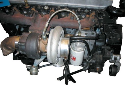
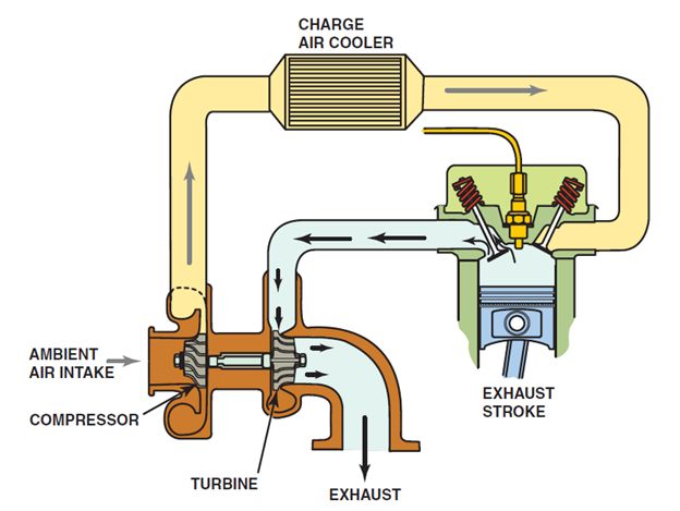
A turbocharger greatly increases engine power by pumping additional compressed air into the combustion chambers. This allows a greater quantity of fuel to be burned in the cylinders resulting in greater power output. In a turbocharger, the turbine wheel spins as exhaust gas flows out of the engine and drives the turbine blades. The turbine spins the compressor wheel at the opposite end of the turbine shaft, pumping air into the intake system.

Cummins Diesel Turbocharger

This figure shows an air charge cooler that is used to cool the compressed air.

Air Charge Cooler

The first component in a typical turbocharger system is an air filter through which ambient air passes before entering the compressor. The air is compressed, which raises its density (mass/unit volume). All currently produced light-duty diesels use an air charge cooler whose purpose is to cool the compressed air to further raise the air density. Cooler air entering the engine means more power can be produced by the engine.

Diesel Air Charge Cooler Compressed Air

This figure shows an air charge cooler that is used to cool the compressed air.

Next Steps towards ASE Certification

Now that you’re familiar with Diesel Engine Turbochargers, try out our free Automotive Service Excellence Tests to see how much you know!

Diesel Injector Nozzles Explained (With Diagram)

Parts Involved

Diesel injector nozzles are spring-loaded closed valves that spray fuel directly into the combustion chamber or precombustion chamber when the injector is opened. Injector nozzles are threaded or clamped into the cylinder head, one for each cylinder, and are replaceable as an assembly.

The tip of the injector nozzle has many holes to deliver an atomized spray of diesel fuel into the cylinder of the Engine. Parts of a diesel injector nozzle include:

  • Heat shield. This is the outer shell of the injector nozzle and may have external threads where it seals in the cylinder head.
  • Injector body. This is the inner part of the nozzle and contains the injector needle valve and spring, and threads into the outer heat shield.
  • Diesel injector needle valve. This precision machined valve and the tip of the needle seal against the injector body when it is closed. When the valve is open, diesel fuel is sprayed into the combustion chamber. This passage is controlled by a computer-controlled solenoid on diesel engines equipped with computer-controlled injection.
  • Injector pressure chamber. The pressure chamber is a machined cavity in the injector body around the tip of the injector needle. Injection pump pressure forces fuel into this chamber, forcing the needle valve open.

Diesel Injector Nozzle Operation

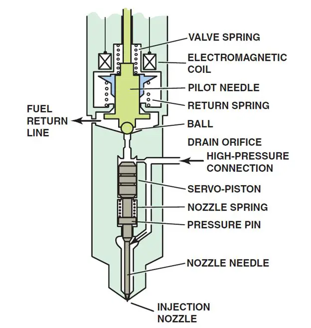
Duramax Diesel Fuel Injector Parts Labeled

Duramax diesel fuel injector showing all of the internal parts.

The electric solenoid attached to the injector nozzle is computer controlled and opens to allow fuel to flow into the injector pressure chamber.

The fuel flows down through a fuel passage in the injector body and into the pressure chamber. The high fuel pressure in the pressure chamber forces the needle valve upward, compressing the needle valve return spring and forcing the needle valve open. When the needle valve opens, diesel fuel is discharged into the combustion chamber in a hollow cone spray pattern. Learn more about Engine Lubrication & Cooling Systems Here.

Any fuel that leaks past the needle valve in the Engine returns to the fuel tank through a return passage and line.

Next Steps towards ASE Certification

Now that you’re familiar with Diesel Injector Nozzles, try out our free Automotive Service Excellence Tests to see how much you know!

Testing for Galvanic Activity and Electrolysis

A voltmeter set to read DC volts is used to test for galvanic activity and electrolysis. To check for excessive voltage caused by galvanic activity or electrolysis, perform the following steps.
STEP 1. Allow the engine to cool and then carefully remove the pressure cap from the radiator.
STEP 2. Set the voltmeter to DC volts and connect the black meter lead to a good engine ground.
STEP 3. Place the red meter lead into the coolant.
STEP 4. Read the meter. If the voltage is above 0.5 V, this indicates excessive galvanic activity. Normal readings should be less than 0.2 V (200 mV). Flush and refill the cooling system.
STEP 5. To test for excessive electrolysis, start the engine and turn on all electrical accessories, including the headlights on high beam.
STEP 6. Read the voltmeter. If the reading is higher than 0.5 V, check for improper body ground wires or connections. Normal readings should be less than 0.3 V (300 mV).

Testing for Galvanic Activity Bi-Metal Corrosion

Galvanic activity is created by two dissimilar metals in contact with a liquid, in this case coolant

Next Steps towards ASE Certification

Now that you’re familiar with bi-metal corrosion in testing for galvanic activity and electrolysis, try out our free Automotive Service Excellence Tests to see how much you know!

Diesel Engine Injection Pump

A diesel engine injection pump is used to increase the pressure of the diesel fuel from very low values from the lift pump to the extremely high pressures needed for injection. Ready for the advanced course? Test your knowledge of A1 – Engines Here.

Need for High-Pressure Fuel Pump

  • The lift pump is a low-pressure, high-volume pump.
  • The high-pressure injection pump is a high-pressure, low-volume pump.

Injection pumps are usually driven by a gear off the camshaft at the front of the engine. As the injection pump shaft rotates, the diesel fuel is fed from a fill port to a high-pressure chamber. If a distributor type injection pump is used, the fuel is forced out of the injection port to the correct injector nozzle through the high-pressure line.

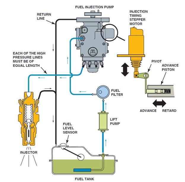
Standadyne Diesel Fuel Injection Pump Assembly

A schematic of a Standadyne diesel fuel-injection pump assembly showing all of the related components.

Distributor Injection Pump

A distributor diesel injection pump is a high-pressure pump assembly with lines leading to each individual injector. The high-pressure lines between the distributor and the injectors must be the exact same length to ensure proper injection timing. The high-pressure fuel causes the injectors to open. Due to the internal friction of the lines, there is a slight delay before fuel pressure opens the injector nozzle.

The injection pump itself creates the injection advance needed for engine speeds above idle often by using a stepper motor attached to the advance piston, and the fuel is then discharged into the lines.

Next Steps towards ASE Certification

Now that you’re familiar with Standadyne diesel fuel-injection pump assemblies, try out our free Automotive Service Excellence Tests to see how much you know!

Principles of Four Stroke Cycle Engine Operation

Principles:

The first four-stroke cycle engine was developed by a German engineer, Nickolaus Otto, in 1876. Most automotive engines use the four-stroke cycle of events. The process begins by the starter motor rotating the engine until combustion takes place. The four-stroke cycle is repeated for each cylinder of the engine.

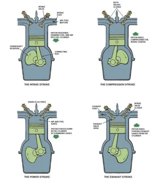
A piston that moves up and down, or reciprocates, in a cylinder can be seen in the following figure. The piston is attached to a crankshaft with a connecting rod. This arrangement allows the piston to reciprocate (move up and down) in the cylinder as the crankshaft rotates.

Operation:

Four Stroke Cycle Engine Operation

A cycle is a complete series of events that continually repeats. Most automobile engines use a four-stroke cycle.

Engine cycles are identified by the number of piston strokes required to complete the cycle. A piston stroke is a one-way piston movement either from top to bottom or bottom to top of the cylinder. During one stroke, the crankshaft rotates 180 degrees (1/2 revolution). A cycle is a complete series of events that continually repeats. Most automobile engines use a four-stroke cycle.

  • Intake stroke. The intake valve is open and the piston inside the cylinder travels downward, drawing a mixture of air and fuel into the cylinder. The crankshaft rotates 180 degrees from top dead center (TDC) to bottom dead center (BDC) and the camshaft rotates 90 degrees.
  • Compression stroke. As the engine continues to rotate, the intake valve closes and the piston moves upward in the cylinder, compressing the air-fuel mixture. The crankshaft rotates 180 degrees from bottom dead center (BDC) to top dead center (TDC) and the camshaft rotates 90 degrees.
  • Power stroke. When the piston gets near the top of the cylinder, the spark at the spark plug ignites the air-fuel mixture, which forces the piston downward. The crankshaft rotates 180 degrees from top dead center (TDC) to bottom dead center (BDC) and the camshaft rotates 90 degrees.
  • Exhaust stroke. The engine continues to rotate, and the piston again moves upward in the cylinder. The exhaust valve opens, and the piston forces the residual burned gases out of the exhaust valve and into the exhaust manifold and exhaust system. The crankshaft rotates 180 degrees from bottom dead center (BDC) to top dead center (TDC) and the camshaft rotates 90 degrees.

This sequence repeats as the engine rotates. To stop the engine, the electricity to the ignition system is shut off by the ignition switch, which stops the spark to the spark plugs. The combustion pressure developed in the combustion chamber at the correct time will push the piston downward to rotate the crankshaft.

Next Steps towards ASE Certification

Now that you’re familiar with the Four Stroke Cycle of Combustion Engines, try out our free Automotive Service Excellence Tests to see how much you know! Test your knowledge of automotive engines in order to Ace the A1 – Engine Repair or A8 – Engine Performance exams!

Engine Lubrication & Cooling Systems

Lubrication System

All engines contain moving and sliding parts that must be kept lubricated to reduce wear and friction. The oil pan, bolted to the bottom of the engine block, holds 4 to 7 quarts (4 to 7 liters) of oil.

An oil pump, which is driven by the engine, forces the oil through the oil filter and then into passages in the crankshaft and block. These passages are called oil galleries. The oil is also forced up to the valves and then falls down through openings in the cylinder head and block, then back into the oil pan.

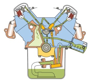
Combustion Engine Lubrication System Diagram

Here is a typical lubrication system, showing the oil pan, oil pump, oil filter, and oil passages

Cooling Systems

All engines must have a cooling system to control engine temperatures. While some older engines were air cooled, all current production passenger vehicle engines are cooled by circulating antifreeze coolant through passages in the block and cylinder head.

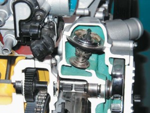
Combustion Engine Coolant System Diagram

The coolant temperature is controlled by the thermostat

The coolant picks up the heat from the engine and after the thermostat opens, the water pump circulates the coolant through the radiator where the excess heat is released to the outside air, cooling the coolant. The coolant is continuously circulated through the cooling system and the temperature is controlled by the thermostat.

The coolant temperature is controlled by the thermostat, which opens and allows coolant to flow to the radiator when the temperature reaches the rating temperature of the thermostat.

Next Steps towards ASE Certification

Now that you’re familiar with Combustion Engine Lubrication & Coolant Systems, try out our free Automotive Service Excellence Tests to see how much you know!