ASE Certification Training Headquarters

Online ASE Certification Training and Career Center

Welcome to ASE Certification Training Headquarters! We have everything you need to make your life easier as you begin your career as an Automotive Service Excellence Certified Master Mechanic. State specific training requirements, a step-by-step hiring process, potential employers, and interviews to help you get hired are just some of the helpful things you'll find here.

Water Pumps in Automotive Engine Coolant Systems

Operation

The water pump (also called a coolant pump) is driven by one of two methods.

  • Crankshaft belt
  • Camshaft

Coolant recirculates from the radiator to the engine and back to the radiator. Low-temperature coolant leaves the radiator by the bottom outlet. It is pumped into the warm engine block, where it picks up some heat. From the block, the warm coolant flows to the hot cylinder head, where it picks up more heat.

  • NOTE: Some engines use reverse cooling. This means that the coolant flows from the radiator to the cylinder head(s) before flowing to the engine block.
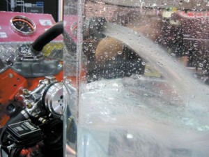
Coolant Flow Demonstration Automotive Engine

A demonstration engine running on a stand showing the amount of coolant flow that actually occurs through the cooling system.

Frequently Asked Quesiton: How much Coolant Can a Water Pump Move?

A typical water pump can move a maximum of about 7,500 gallons (28,000 liters) of coolant per hour, or recirculate the coolant in the engine over 20 times per minute. This means that a water pump could be used to empty a typical private swimming pool in an hour! The slower the engine speed, the less power is consumed by the water pump. However, even at 35 mph (56 km/h), the typical water pump still moves about 2,000 gallons (7,500 liters) per hour or 0.5 gallon (2 liters) per second!


Water pumps are not positive displacement pumps. The water pump is a centrifugal pump that can move a large volume of coolant without increasing the pressure of the coolant. The pump pulls coolant in at the center of the impeller. Centrifugal force throws the coolant outward so that it is discharged at the impeller tips.

As engine speeds increase, more heat is produced by the engine and more cooling capacity is required. The pump impeller speed increases as the engine speed increases to provide extra coolant flow at the very time it is needed.

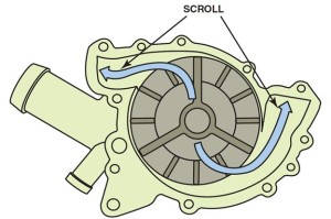
Coolant Pump Impeller and Scroll V-Type Engine

Coolant flow through the impeller and scroll of a coolant pump for a V-type engine

Coolant leaving the pump impeller is fed through a scroll. The scroll is a smoothly curved passage that changes the fluid flow direction with minimum loss in velocity. The scroll is connected to the front of the engine so as to direct the coolant into the engine block. On V-type engines, two outlets are often used, one for each cylinder bank. Occasionally, diverters are necessary in the water pump scroll to equalize coolant flow between the cylinder banks of a V-type engine in order to equalize the cooling.

Water Pump Service

A worn impeller on a water pump can reduce the amount of coolant flow through the engine.

If the seal of the water pump fails, coolant will leak out of the weep hole. The hole allows coolant to escape without getting trapped and forced into the water pump bearing assembly.

The hole allows coolant to escape without getting trapped and forced into the water pump bearing assembly.

If the bearing is defective, the pump will usually be noisy and will have to be replaced. Before replacing a water pump that has failed because of a loose or noisy bearing, check all of the following:

  1. Drive belt tension
  2. Bent fan
  3. Fan for balance

If the water pump drive belt is too tight, excessive force may be exerted against the pump bearing. If the cooling fan is bent or out of balance, the resulting vibration can damage the water pump bearing.

Tech Tip: Release the Belt Tension before Checking a Water Pump

The technician should release water pump belt tension before checking for water pump bearing looseness. To test a water pump bearing, it is normal to check the fan for movement; however, if the drive belt is tight, any looseness in the bearing will not be felt.

Next Steps towards ASE Certification

Now that you’re familiar with Water Pumps in Automotive Engine Coolant Systems, try out our free Automotive Service Excellence Tests to see how much you know!

Radiators in Automotive Engines

Types of Radiator Cores

The two types of radiator cores in common use in most vehicles are:

  • Serpentine fin core
  • Plate fin core

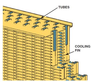
In each of these types, the coolant flows through oval-shaped core tubes. Heat is transferred through the tube wall and soldered joint to cooling fins. The fins are exposed to the air that flows through the radiator, which removes heat from the radiator and carries it away.

Engine Radiator Core Fins and Tubes

The tubes and fins of the radiator core.

Since the 1980s, most radiators have been made from aluminum with nylon-reinforced plastic side tanks. These materials are corrosion resistant, have good heat transferability, and are easily formed.

Core tubes are made from 0.0045 to 0.012 in. (0.1 to 0.3 mm) sheet brass or aluminum, using the thinnest possible materials for each application. The metal is rolled into round tubes and the joints are sealed with a locking seam.

The two basic designs of radiators include:

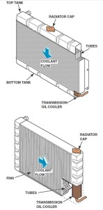
  1. Down-flow radiators. This design was used mostly in older vehicles, where the coolant entered the radiator at the top and flowed downward, exiting the radiator at the bottom.
  2. Cross-flow radiators. Most radiators use a cross-flow design, where the coolant flows from one side of the radiator to the opposite side.
Down-Flow and Cross-Flow Radiators

A radiator may be either a down-flow or a cross-flow type.

How Radiators Work

The main limitation of heat transfer in a cooling system is in the transfer from the radiator to the air. Heat transfers from the water to the fins as much as seven times faster than heat transfers from the fins to the air, assuming equal surface exposure. The radiator must be capable of removing an amount of heat energy approximately equal to the heat energy of the power produced by the engine. Each horsepower is equivalent to 42 BTUs (10,800 calories) per minute. As the engine power is increased, the heat-removing requirement of the cooling system is also increased.

With a given frontal area, radiator capacity may be increased by increasing the core thickness, packing more material into the same volume, or both. The radiator capacity may also be increased by placing a shroud around the fan so that more air will be pulled through the radiator.

  • NOTE: The lower air dam in the front of the vehicle is used to help direct the air through the radiator. If this air dam is broken or missing, the engine may overheat, especially during highway driving due to the reduced airflow through the radiator.

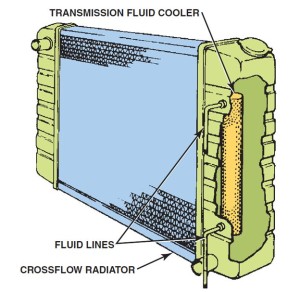
When a transmission oil cooler is used in the radiator, it is placed in the outlet tank, where the coolant has the lowest temperature.

Transmission Fluid Cooler in Radiator Tank

Many vehicles equipped with an automatic transmission use a transmission fluid cooler installed in one of the radiator tanks.


Pressure Caps

Operation

On most radiators the filler neck is fitted with a pressure cap. The cap has a spring-loaded valve that closes the cooling system vent. This causes cooling pressure to build up to the pressure setting of the cap. At this point, the valve will release the excess pressure to prevent system damage. Engine cooling systems are pressurized to raise the boiling temperature of the coolant.

  • The boiling temperature will increase by approximately 3°F (1.6°C) for each pound of increase in pressure.
  • At sea level, water will boil at 212°F (100°C). With a 15 PSI (100 kPa) pressure cap, water will boil at 257°F (125°C), which is a maximum operating temperature for an engine.

Functions

The specified coolant system temperature serves two functions.

  1. It allows the engine to run at an efficient temperature, close to 200°F (93°C), with no danger of boiling the coolant.
  2. The higher the coolant temperature, the more heat the cooling system can transfer. The heat transferred by the cooling system is proportional to the temperature difference between the coolant and the outside air. This characteristic has led to the design of small, high-pressure radiators that are capable of handling large quantities of heat. For proper cooling, the system must have the right pressure cap correctly installed.

A vacuum valve is part of the pressure cap and is used to allow coolant to flow back into the radiator when the coolant cools down and contracts.

  • NOTE: The proper operation of the pressure cap is especially important at high altitudes. The boiling point of water is lowered by about 1°F for every 550 ft increase in altitude. Therefore, in Denver, Colorado (altitude 5,280 ft), the boiling point of water is about 202°F, and at the top of Pike’s Peak in Colorado (14,110 ft) water boils at 186°F.

Metric Radiator Caps

According to the SAE Handbook, all radiator caps must indicate their nominal (normal) pressure rating. Most original equipment radiator caps are rated at about 14 to 16 PSI (97 to 110 kPa).

Metric Radiator Caps

The pressure valve maintains the system pressure and allows excess pressure to vent. The vacuum valve allows coolant to return to the system from the recovery tank.

However, many vehicles manufactured in Japan or Europe use radiator pressure indicated in a unit called a bar. One bar is the pressure of the atmosphere at sea level, or about 14.7 PSI. The conversions can be used when replacing a radiator cap, to make certain it matches the pressure rating of the original.

  • NOTE: Many radiator repair shops use a 7 PSI (0.5 bar) radiator cap on a repaired radiator. A 7 PSI cap can still provide boil protection of 21°F (3°F x 7 PSI = 21°F) above the boiling point of the coolant. For example, if the boiling point of the antifreeze coolant is 223°F, then 21°F is added for the pressure cap, and boilover will not occur until about 244°F (223°F + 21°F = 244°F). Even though this lower pressure radiator cap provides some protection and will also help protect the radiator repair, the coolant can still boil before the “hot” dash warning light comes on and, therefore, should not be used. In addition, the lower pressure in the cooling system could cause cavitation to occur and damage the water pump. For best results, always follow the vehicle manufacturer’s recommended radiator cap.

Working Better Under Pressure

A problem that sometimes occurs with a high-pressure cooling system involves the water pump. For the pump to function, the inlet side of the pump must have a lower pressure than its outlet side. If inlet pressure is lowered too much, the coolant at the pump inlet can boil, producing vapor. The pump will then spin the coolant vapors and not pump coolant. This condition is called pump cavitation. Therefore, a radiator cap could be the cause of an overheating problem. A pump will not pump enough coolant if not kept under the proper pressure for preventing vaporization of the coolant.

Next Steps towards ASE Certification

Now that you’re familiar with Radiators in Automotive Engines, try out our free Automotive Service Excellence Tests to see how much you know!